详情
Overview
Cooling towers recirculation water is large in volumes and
gets easily contaminated with suspended solids, atmospheric dust,
microbiological organisms, various airborne debris and sometime
particulate of rusted metal coming out from heat exchangers. These
contamination and impurities get settled either in cooling tower
pond or deposit on the surface of Heat exchangers and significantly
decrease the performance of cooling tower circuit. Under these
circumstances, significant improvement might be realized with the
use of a side stream filter and pond cleaning accessories.
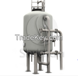
Our unique design of Side Stream Filter and cooling tower pond
accessories ensures efficient & effective removal of suspended
solids & other contaminations and reinforce healthy conditions
of cooling tower and associated heat exchangers.
Shubham SSFs are available in diameters from 0.**5 Mts. to 4.0
Mts.(vertically) and in length from 3.0 Mts. mm to *1 Mts.
(Horizontally) with flow ratesup to **0M3/Hr. These rugged,
pre-engineered, pre-assembled units minimize installation and
start-up costs.
Working Principle
Water from the system is pumped through the top of the filter
tank and distributed evenly over the media. Suspended particles are
trapped in the filter media. The filtered water then passes
through the media bed and reaches under drain assembly at the
bottom of the filter and returns to the piping system.
Type of Installation
Direct piping connection: Inlet and outlet of SSF are directly
connected to main stream pipe and utilize main stream pumps for
further filtration process which eliminates the requirement of
extra pumps.
Cooling tower pond Connection: This type of installation need
additional pump which is directly connected to cooling tower pond
at suction side and feed water into SSF for further filtration
process and filtered water goes back to the cooling tower pond at
the opposite of pump suction.This recirculates entire pond volume
and does not depend on main stream pump and its operation.
Flow : 1M3/Hr. - **0 M3/Hr.
Inlet TSS : Up to *0 Mg/L
Inlet Turbidity : Up to *0 NTU
Filtration Velocity : *8 to *0 M3/Hr./M2
Diameter (Vertical Vessel) : 0.**5 Mts. - 4.0 Mts.
Length (Horizontal Vessel) : 3.*0 Mts. - *1.0 Mts. MOC : FRP /
Mid Steel / Stainless Steel Coating /
lining : Epoxy / FRP / Rubber Lined
Filtration Rating : Up to *0 Micron
Design Code : ASME / IS
Design Pressure : Up to *0 Bar
Working Pressure : 1.1 to 3.5 Bar
Clear Pressure Drop : 0.3 bar
Top distribution system : bell mouth
Bottom distribution system : Strainer plate or Header &
laterals.
Key Features
• Simple design maximizes reliability and efficiency
• Two or Multi layers of filtration media
• Filtration rating up to *0 *0 Microns
• Standard and effective quartz sand media.
• Low Pressure drop across the vessel
• FRP, MSRL, MSEP & SS Vessels are available.
• Manual, Semi-Automatic and Automatic features are
provided
• Pre-assembled construction minimizes start-up time and
installation costs
• Structural steel legs provide rigid support of vessel for
safety
• Air scouring available for high flow pressure vessel.
• Proven design of internal distribution and collection
system.
Benefits
• Reduced Corrosion Rates
• Increased Equipment Life
• Better System Efficiency
• Reduced Maintenance Costs
• Better Chemical Control
• Reduce overall chemical cost
• Reduce Cleaning frequency
• Maintain Temperature variation.
Applications
Cooling Tower & Process Water Treatment
• Turbidity & Total Suspended Solid Removal
• Side Stream Filter
• Full Stream Filter
• Make up water Filter
WHY & WHEN SIDESTREAM FILTERS?
The installation of a sidestream filter is a capital expense,
which may be hard to justify in most plants. Consider the following
as indications that a plant should look into the possibility of
installing a filter.
The primary makeup is from an unclarified water source (river,
sewage treatment, etc.) that is high in suspended solids and/or
iron.
• The system is having a difficult biological problem even
though a good biocide program is in effect.
• Heat exchangers are opening dirty even though a good
antifoulant program is being used.
• Excessive corrosion rates can be traced to fouling.
• Loss of heat transfer is attributed to deposition rather
than corrosion.
• High levels of solids are building up in the sump.
• Heat exchangers require frequent mechanical cleanings.
